
Microwave Ceramics and Modules
Filter
2 Pole Filter for Cordless phone [5.86≠5.875] Bandpass
B69842N5867A315
Preliminary Datasheet
ISSUE DATE
27.05.03
ISSUE
P1
PUBLISHER
SAW MWC PD F
PAGE
1/4
Features
SMD filter consisting of coupled resonators with stepped impedances
MgTiO3 - CaTiO3 (
r = 21 / TCf =0±10 ppm/K) with a coating of copper (10
µ
m) and tin (>5
µ
m)
Excellent reflow solderability, no migration effect due to copper/tin metallization
Index
Page
2
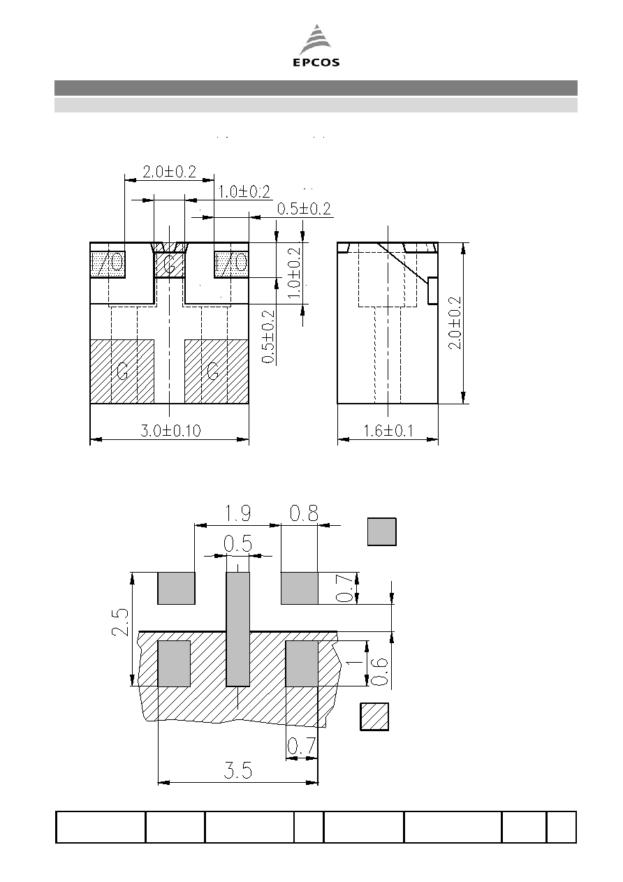
Component drawing
Recommended footprint
Page
3
Characteristics
Maximum ratings
Typical passband characteristic
Page
4
Processing information
Soldering requirements
Delivery mode
Microwave Ceramics and Modules
Filter
2 Pole Filter for Cordless phone [5.86≠5.875] Bandpass
B69842N5867A315
Preliminary Datasheet
ISSUE DATE
27.05.03
ISSUE
P1
PUBLISHER
SAW MWC PD F
PAGE
2/4
Component drawing
Recommended footprint
Soldered Pads.
I/O Pads must be
connected to 50 ohms
impedance lines.
ground covered with solder
resist. It must be
connected to groung plane
below by vias
Max diameter: 0.3 mm
Max via pitch:1 mm
FOOTPRINT_130802.DWG WMF

Microwave Ceramics and Modules
Filter
2 Pole Filter for Cordless phone [5.86≠5.875] Bandpass
B69842N5867A315
Preliminary Datasheet
ISSUE DATE
27.05.03
ISSUE
P1
PUBLISHER
SAW MWC PD F
PAGE
3/4
Characteristics
min.
typ.
max.
Center frequency
fc - 5867.5
- MHz
Insertion loss
IL 1.2
1.4
dB
Passband
B 15 MHz
Standing wave ratio
SWR 1.5
2.0
Impedance
Z 50
Power P
1.0
W
Attenuation
at 4061.5 MHz
at 5732.5 MHz
40
8
dB
dB
Maximum ratings
IEC climatic category (IEC 68-1)
- 40/+ 90/56
Operating temperature
Top -40 / + 85
∞C
Typical passband characteristic
t.b.d.

Microwave Ceramics and Modules
Filter
2 Pole Filter for Cordless phone [5.86≠5.875] Bandpass
B69842N5867A315
Preliminary Datasheet
ISSUE DATE
27.05.03
ISSUE
P1
PUBLISHER
SAW MWC PD F
PAGE
4/4
Processing information
Wettability to IEC 68-2-58:
75% (after aging)
Soldering requirements
Soldering type
reflow
Maximum soldering temperature 235
(max. 2 sec.) ∞C
(measuring point on top surface of the component)
225 (max. 10 sec.)
∞C
Recommended soldering conditions (infrared):
20-40 sec.
40-80 sec.
within 10 sec.
Time [sec.]
Temp. [∞C]
215∞C±10∞C
LOETPROF.DOC
Delivery mode
Blister tape acc. to IEC 286-3, PS, grey
Pieces/tape: 4000.
t.b.d.
EPCOS AG 2001. All Rights Reserved. Reproduction, publication and dissemination of this data sheet, enclosures hereto
and the information contained therein without EPCOS' prior express consent is prohibited.
The information contained in this data sheet describes the type of component and shall not be considered as guaranteed
characteristics. Purchase orders are subject to the General Conditions for the Supply of Products and Services of the
Electrical and Electronics Industry recommended by the ZVEI (German Electrical and Electronic Manufacturers'
Association), unless otherwise agreed.